Our Unit Converter
The ESI Unit converter allows you to quickly and easily access a conversion tool to work out your preferred unit of pressure measurement wherever you may be. Whether out on-site or in the office.
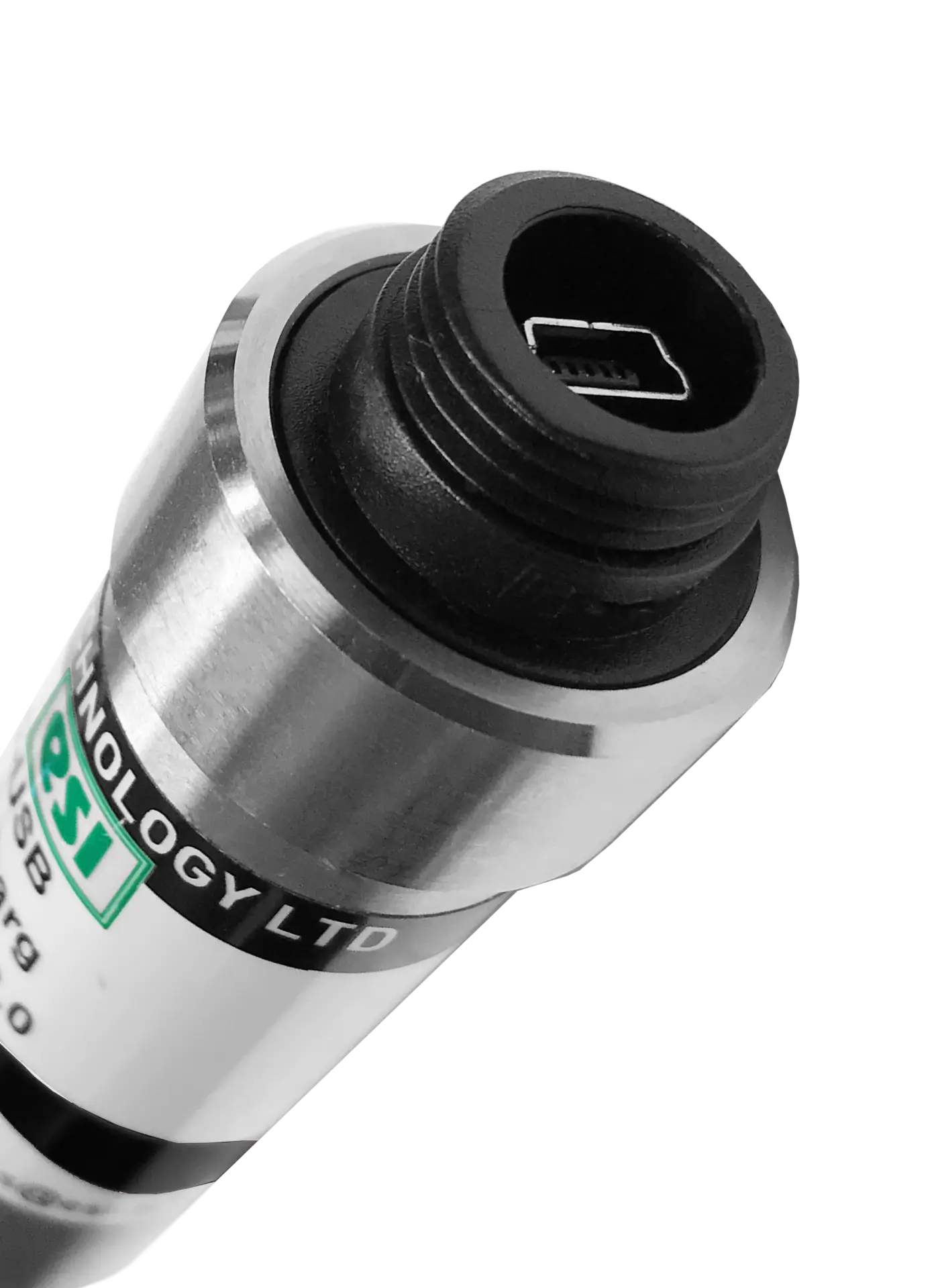
Download the ESI-USB© Software
The ESI-USB© software allows you to connect your ESI transducer to your laptop or PC and be up and running monitoring pressure data within ten minutes. The software auto-updates and is compatible with Windows 8, 10 & 11.
Pressure Transducer/Transmitter Installation Guide
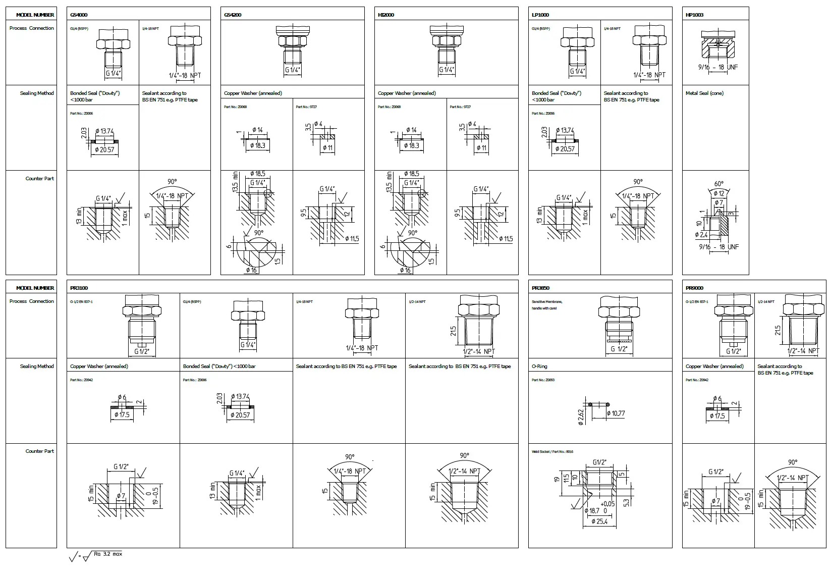
GS4000 Series | GS4200 Series | HI2000 Series | LP1000 Series | HP1000 Series | PR3100 Series | PR3850/3860 Series | PR9000/9500 Series
Installing a pressure transducer correctly is essential to ensure accurate readings, reliable performance, and long operational life. A transducer is a precise measuring instrument, and even small installation errors can lead to inaccurate data, premature wear, or complete device failure. Taking the time to follow best practices during installation not only protects your investment but also helps maintain the safety and efficiency of your system.
Correct installation ensures that the transducer is positioned and secured in a way that avoids unnecessary strain on the sensing element. Factors such as over-tightening, incorrect sealing methods, or exposure to excessive vibration can affect measurement accuracy and cause long-term damage. The process also involves ensuring electrical connections are secure and protected from moisture, dust, and other environmental hazards that may interfere with signal transmission.
Another important consideration is the location of the pressure transducer within your system. Placing it in an area with stable conditions, away from sources of extreme heat, cold, or pulsation, will help maintain consistent readings. In applications involving fluids, ensuring the transducer is mounted so that the sensing port remains free from trapped air or debris is vital for precise pressure measurement.
Correct installation also plays a role in reducing downtime and maintenance costs. A well-installed pressure transducer will require fewer adjustments and is less likely to experience unexpected failures. This contributes to overall system reliability, especially in critical applications where accurate pressure monitoring is essential for safety and compliance.
By following the proper installation guidelines outlined in this guide, you can ensure your pressure transducer delivers optimal performance throughout its service life. The time and care you invest at the start will pay off in the form of accurate, dependable measurements and smooth, trouble-free operation.
Below is our installation guide for the following standard models
GS4000 | GS4200 Series | LP1000 Series | HP1000 Series | PR3100 Series | PR3850/3860 | PR9000/ 9500 Series
-
Intended Use
Please refer to datasheet, calibration certificate and installation instructions before starting installation.
The Device must be used within the specified pressure range, temperature and supply voltage.
-
Installation
During Installation, please comply with the relevant national guidelines.
Installer must be technically competent and familiar with pressure monitoring technology.
-
Mechanical Installation
Ensure system is not pressurised before installation.
Ensure the measurement cell is not damaged before installation.
Use the correct sized AF wrench on the hexagon with tightening torque in accordance with table 1. The customer must ensure that the pressure seal is suitable for the application.
See tightening torque setting guidelines in table 1 below.
-
Electrical Installation
Remaining media in the pressure port may be hazardous so handle with care.
Refer to product calibration certificate for wiring diagram.
Ensure electrical connector and cable gland are securely fitted and sealed.
-
Maintenance
Recalibration interval depends on own industry guidelines.
Do not insert pointed or hard objects in to the pressure port.
Repairs must be carried out by manufacturer only.
-
Removal/ End of Life
Ensure system is de-pressurised before removal
Remaining media in the pressure port may be hazardous so handle with care.
Can be returned to factory at end of life for cleaning.
-
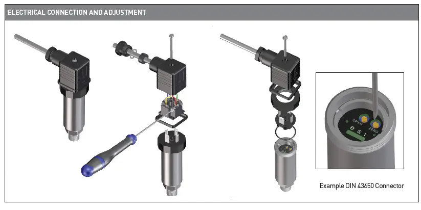
Electrical Connection and Adjustment

-
Threads and Sealing

-
Tightening Torque
Torque Settings*
Thread Type P<100bar 100bar<400bar 600bar<1500bar 2000bar 4000/ 5000bar*** G1/4″ (BSPP), 1/4-18 NPT** Max. 35 Nm — — G1/2″ (BSPP), 1/2-14 NPT** Max. 50 Nm F250C (9/16- 18 UNF female conical) — — 30-35 Nm 32-35 Nm*** * The torque values apply only to test conditions, and are a guide only. Tightening torques for installation depend on many factors including materials, lubrication, coating and surface treatment. If in doubt consult manufacturer.
** NPT threads need an additional seal to BS EN 751 (e.g. PTFE tape)
*** Tightening torque and maximum pressure should be in accordance with high pressure pipe supplier’s documentation.Materials of the mating part should be selected to suit pressure and media requirements.
-
Disclaimer
ESI Technology Ltd operates a policy of continuous improvement and product development. We reserve the right to change specification and operating instructions without prior notice.
Please observe applicable safety regulations when installing or removing the pressure transmitter or transducer.
ESI Technology Ltd operates a policy of continuous improvement and product development. We reserve the right to change specification and operating instructions without prior notice.
Please observe applicable safety regulations when installing or removing the pressure transmitter or transducer.
Need more information? Check our Product Datasheets for unit specifications
Product Datasheets