Din Connectors
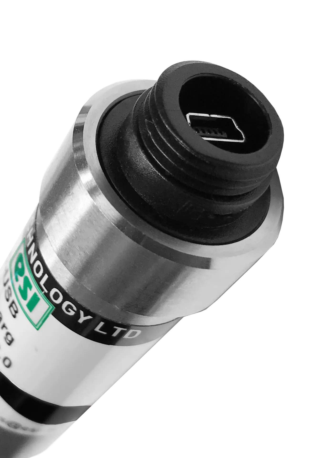
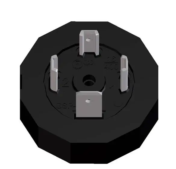
A DIN connector is an electrical connector that was originally standardized by the Deutsches Institut für Normung (DIN) organization. The general electrical connector used by ESI is to EN175301-803 (ex DIN43650) DIN Standard.
The ESI Unit converter allows you to quickly and easily access a conversion tool to work out your preferred unit of pressure measurement wherever you may be. Whether out on-site or in the office.
The ESI-USB© software allows you to connect your ESI transducer to your laptop or PC and be up and running monitoring pressure data within ten minutes. The software auto-updates and is compatible with Windows 8, 10 & 11.
A DIN connector is an electrical connector that was originally standardized by the Deutsches Institut für Normung (DIN) organization. The general electrical connector used by ESI is to EN175301-803 (ex DIN43650) DIN Standard.
| Output |
| 4-20 mA |
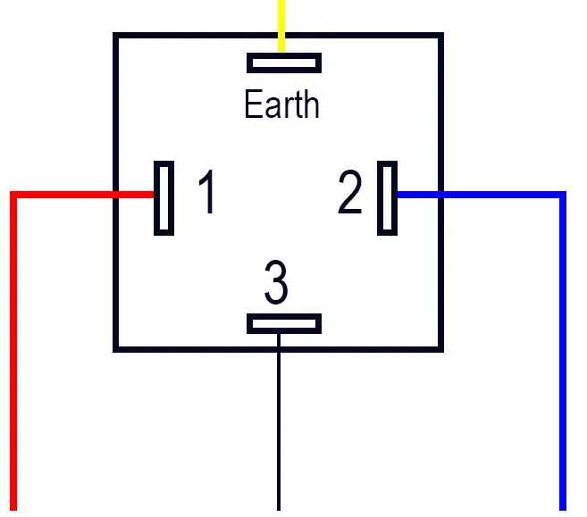
Wire Key – 2 Wire
| Earth | Yellow or White | — |
| 1 | Red | + Supply |
| 2 | Blue | + Signal Output |
| 3 | Not Connected | — |
Output 4-20 mA
| Output |
|---|
| 0-5 Vdc |
| 0-10 Vdc |
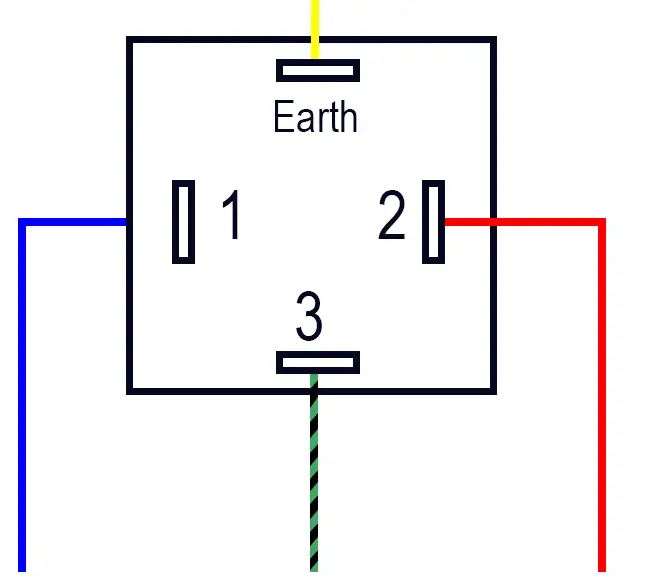
Wire Key – 3 Wire
| Earth | Yellow or White | Or Earth Not Connected |
| 1 | Blue | + Supply |
| 2 | Red | + Supply |
| 3 | Black or Green | + Signal Output |
Output 4-20 mA
| Output |
|---|
| Unrat mV |
| 0-20 mV |
| 0-100 mV |
| 0-5 Vdc |
| 0-10 Vdc |
Wire Key – 4 Wire
| Earth | Yellow or White | – Signal Output |
| 1 | Blue | – Supply |
| 2 | Red | + Supply |
| 3 | Black or Green | + Signal Output |
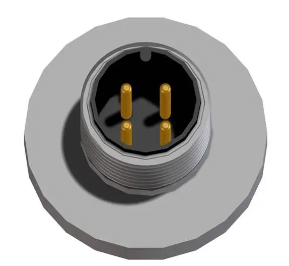
An M12 Connector has a locking thread that is used primarily in production equipment as standard.
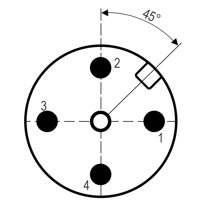
| 2 Pin (4-20mA) | 3 Pin (Vdc) | 4 Pin (Vdc) |
|---|---|---|
| 1: +ve Supply | 1: -ve Supply | 1: -ve Supply |
| 2: n/c | 2: +ve Supply | 2: +ve Supply |
| 3: lout | 3: +ve Output | 3: +ve Output |
| 4: Not Connected | 4: Not Connected | 4: -ve Output |
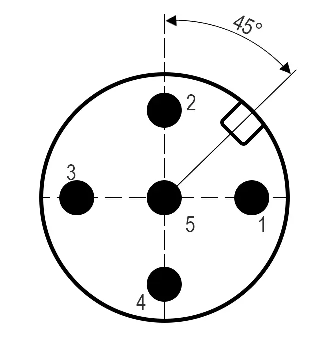
| Pin No | Designation |
|---|---|
| 1 | RS485(B) |
| 2 | RS485(A) |
| 3 | Common Ground |
| 4 | DS Power IN |
| 5 | Analogue Output |
| Case | Case GND |
Output 4-20 mA
| Output |
|---|
| Unrat mV |
| 0-20 mV |
| 0-100 mV |
| 0-5 Vdc |
| 0-10 Vdc |
Wire Key – 4 Wire
| Earth | Yellow or White | – Signal Output |
| 1 | Blue | – Supply |
| 2 | Red | + Supply |
| 3 | Black or Green | + Signal Output |
The wiring used varies dependent on aspects such as output type, voltage, and current requirements; however, we also manufacture custom wiring based on specific customer requirements.
Need something Specific?
Get in touch with our sales team to discuss your options.